BS 7036 Information


 BS 7036-1996

BS 7036:1996 is the code of practice for safety at powered doors for pedestrian use. It is published in five parts, part one is general, parts two to five are specific to door type.

It is not a mandatory requirement to adhere to it’s recommendation but it is a generally accepted wisdom to do so and most often a specified requirement. Should an action be brought as the result of an incident the standard will certainly be referenced by investigators.


Part 1: General
This part of the standard sets provides guidance on general safety recommendations and definitions of terminology used throughout parts 1 to 5.
 
Environment and Management:
Under this section the responsibilities of the specifier (person or organisation responsible for specifying the type of door to be used) are set out for the design/specification stage:
 
>     It is the specifier’s responsibility to ensure an installation conforms to the standard.
>     The specifier should carry out a full Hazard Analysis and Risk Assessment for the proposed installation taking into account the type and volume of traffic.
>    The specifier should seek advice from automatic door specialists and other authorities when planning an installation.
 
Congestion:
>     Congestion in the vicinity of automatic door should be avoided through careful planning of the area.
>     Obstructions, distractions, traffic flow and user characteristics should all be taken into account by the specifier. 
 
Installation and site acceptance:
>     Installation should be by trained and ADSA authorised engineers.
>     On completion an authorised technician checklist completed.
>     A copy should be held by the building owner/specifier for his records.
 
Occupier safety checks:
>     Operation of automatic doors should be regularly checked and records kept by the building owner/occupier.
 
Maintenance:
>     All automatic door installation should regularly maintained.
 
Electrical Design:
>     Electrical Installation to the point of supply should conform to current electrical installation legislation and standards.
>     The electrical supply should be protected with a 30mA RCD.
>     An isolator should be provided adjacent to the door.
 
Activation Systems:
>     Activation systems should open the door in time for persons to pass through the door without hesitation.
>     Manual activation systems such as push switches should be positioned where the user can see the door and will not be hit by it.
 
Safety Devices:
>     Where practicable safety devices should be monitored by the control system so that if a fault occurs the door stops operating in a safe position.
>     When a safety sensor is activated the door motion should stop or reverse direction.
>     Emergency stop devices should stop movement of the door until reset.
>     Presence sensors are used to detect slow moving and stationary traffic and should do so for a minimum of 30 seconds.
 
Drive Controls
The drive control system should be adjustable to limit the speed and maximum static force that the door can exert and thereby limit the maximum Kinetic energy dissipated by the door movement.

 
Maximum Kinetic Energy Levels (Joules)
Maximum Static Entrapment (Newtons)
 
Check Speed
Max Speed
 
Sliding / folding doors
0.17
3.4
150
Swing / balanced doors
0.17
3.4
150
Revolving doors
0.17
10
150
Low energy swing doors
0.17
1.6
67

Construction and Placing of Barriers:
Barrier should:
>     Conform to current legislation and standards.
>     Be a minimum of 900 mm high.
>     Be capable of resisting a horizontal force of at least 740 N/m applied to the top edge.
 
Signage:
The building owner/occupier is responsible for the display and maintenance of signage.
Signage should be affixed to the powered door system at a height of between 1300 mm and 1600 mm.
Appropriate signage includes:
>     No entry sign
>     Keep clear sign
>     Emergency break-out sign
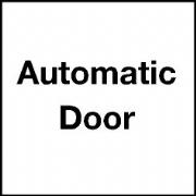
>     Automatic door sign
>     Handicapped sign
>     Direction of travel sign


Part 2: Straight and Curved Sliding Doors and Prismatic and Folding Doors
 
Safety during the opening cycle:
>     Where practicable, one of the following should be fitted:

  • A suitable barrier, the distance between the barrier and the fully open door should be greater than 25mm and less than 100mm.
  • A pocket screen of minimum height 1500 mm
  • Presence sensors

>     Leaf opening speed should be limited to 500mm/s
 
Minimise body traps:

>     If the gap between the face of the door and the structure across which it slides is less than 100 mm, the gap between the rear edge of the door in the fully open position and the fixed structure should be greater than 200 mm.
>     If the gap between the face of the door and the structure across which it slides is greater than 100 mm, the gap between the rear edge of the door in the fully open position and the fixed structure should be greater than 500 mm.
 
Minimise finger traps & drawing in hazards
>    When door is fully open there should be gap of at least 25mm between the stile and jambs.
>     The clearance between the face of the jambs and the face of the leaf glazing should be greater than 25mm.
>     The door should be stopped a minimum of 25mm short of a mullion or structural return, unless this area is protected by a pocket screen.
>     When a folding door is in the open position there should be a gap of at least 25mm between the hinge and the leading stile.
>    Activation of the door should start when the user is 1400mm from the door when approaching the door directly and 700mm when approached from the side.
 
Safety during the closing cycle:
>     One of the following means should be used to prevent doors shutting on traffic during the opening cycle:

  • A hold-open beam positioned between the jambs at a height between 300mm and 600mm above FFL.
  • Presence sensing safety devices should be used.

>     Where the Hazard Analysis & Risk assessment concludes a significant amount of elderly, infirm, disabled or children will use the door, then presence sensors should be used.
>     Presence sensors should detect stationary traffic for a minimum of 30 seconds.
>     The drive control systems should be adjustable to limit the maximum static entrapment force to 150N.
 
Means of Escape:
>     If powered doors are intended as a means of escape from a building then the doors should be either:

  • Capable of manual breakout in the direction of escape.
  • Linked to the fire alarm system in order to open the door on activation of the alarm.

Break-out:
>     The door should stop when break-out is used.
>     The resistance to breakout should not be greater than 220N at the leading or meeting stile.
 
Power failure:
>     A monitored back up system (i.e. Battery pack) should be used for main power failure operation. The system should self monitor and open the door if a fault occurs.


Part 3: Swing doors and Balanced doors:
 
Safety during the opening and closing cycle:
>     One of the following safety devices should be fitted:

  • A presence sensing device to stop door movement ie safety sensors fitted to the top rail of the door leaf.
  • A presence sensing device or safety mat which gives limited protection by preventing a fully open or closed door from moving.

>     If the door can be approached from side when open a barrier should be installed.
>     The dimension between the barrier and fully open door should be between 25mm and 50mm.
>     The maximum Kinetic energy dissipated by the door movement to should be limited 3.4 Joules at maximum speed.
>     The maximum static entrapment force should not exceed 150N
>     Activation of the door should start when the user is 1400mm from the line of the door, when the door opens away from the user.
>     When the door opens towards user activation of the door should start 1400mm from the leading edge of door in the open position.
 
Finger Traps:
>     Finger trap protection should be fitted.
 
Means of Escape:
>     If doors are on an escape route they should open in direction of escape, else be fitted with a break-out system.


Part 4: Low energy doors:
Low energy swing doors are usually installed without door mounted safety because the low kinetic energy levels are not considered dangerous.
The use of low energy doors with out safety sensors should only be considered where the specifier’s Hazard & Risk Assessment concludes it is safe to do so.
Because the drive force is limited, low energy drives are not generally suitable for use on external doors or those otherwise exposed to wind or pressure differences.
 
Safety during the opening and closing cycle:
>     The maximum static entrapment force should not exceed 67N when applied 25mm from the leading or meeting stile of the door
>     Maximum Kinetic energy level should be limited to 1.6Joules.
>     If automatic activation devices are fitted they should be activated:

  • 1400 mm from the door measured perpendicular to the plane of the closed door, where the door opens away from the user.
  • 1400 mm from the leading edge of the door in the fully open position when the door opens towards the user.

>     The door hold open time should be set to 5 seconds or higher to suit the users requirements
 
Finger Traps:
>     Finger trap protection should be fitted.
 
Means of Escape:
>     If doors are on an escape route they should open in direction of escape.
>     Force required to open door manually should be less than 90N at the leading stile.


Part 5: Revolving Doors:
 
For revolving doors the hazards and risks can be greater than for other types of doors and extra care should be taken when considering their use.
 
SECTION 1 - General
 
Safety during the opening cycle:
>     The maximum speed should not be greater than 750mm per second at the outer edge of door leaf, a reference table is provided
>     When a stop signal is given a revolving door should stop within 5.7 degrees of rotation
>     Leading mullions should have a 25mm rubber buffer fitted
>     Gap between door leaf edge and drum wall should be at least 30mm
>     Activation of the door should start when the user is 1400mm from a stationary door and 750mm if the door is already turning at slow speed.
>     The speed of door should be adjusted to keep the kinetic energy values below 10 Joules at operating speed and 0.17 Joules in slow speed
>     Max static entrapment force is 150 Newtons (approx15kg)
>     Keep clear sign should be fitted to each door leaf
>     Where fitted the resistance to breakout should not be greater than 220N at the outer edge of door leaf.
 
SECTION 2 – For doors less than 3ooom diameter:
>     Leading mullion should be fitted with safety buffer or presence sensor to stop the door if activated.
>     If the specifier’s Hazard and risk analysis indicates - safety from section 3 should be fitted where possible.
 
SECTION 3 –  For doors greater than 3ooom diameter:
>     Presence sensor to stop the door if activated. Active when door 500mm from mullion
>     Door leaves should have presence se sensors protecting the door face to slow door if activated.
>     Doors  should be fitted with presence se sensors scanning the leading edge of the leaf to stop door if activated.
>     Bottom rail of door leaves should have rubber buffers fitted and device to stop door if contacted
>     An emergency stop bottom is required
>     If door leaves can be folded a locking device (storm lock) may be required to prevent doors from folding under pressure from wind
>     If door leaves can be folded a sensor should stop the door rotation when folded beyond 15 degrees
>     If the gap between bottom of door central core and floor is greater than 10mm a sensor should be fitted to stop the door if activated